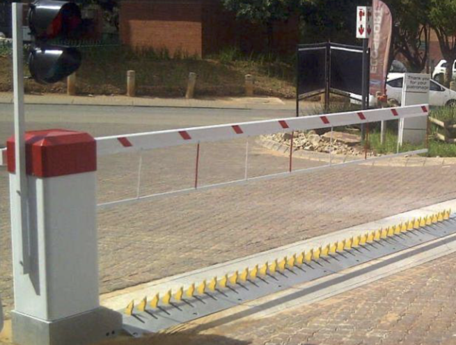
Vehicle Spike Barrier with Drop Arm Barrier
The Madoors USA Vehicle Spike Barrier with Drop Arm Barrier is a 100% locally manufactured, integrated combined access control system pairing an automatic tyre killer road spike barrier with a drop arm boom barrier — both driven by independent single-phase torque motors with 1-second operating speed for the tire killer and 2.5 to 6 seconds for the barrier arm — engineered for 100% duty cycle high-volume traffic applications at industrial facilities, mines, hospitals, casinos, military installations, customs points, embassies, prisons, government premises, banks, cash depots, warehouses, airports, and any high-security access control requirement. The spike barrier is designed to offer bidirectional protection on both entry and exit, with a critical safety sequence ensuring the spikes rise only after the barrier arm has passed through 30 degrees of its closing cycle — preventing spike activation while the barrier arm is still in the vehicle's path.
TECHNICAL SPECIFICATIONS
The Madoors USA integrated spike and drop arm barrier system uses two independent single-phase torque motors — one for the tyre killer spike mechanism and one for the drop arm barrier — providing independent control and operation of each component within the unified access control sequence. The 1-second tyre killer operating speed provides near-instant spike deployment and retraction. The 2.5 to 6 second barrier arm travel speed provides smooth, controlled arm movement across the road width.
The 30-degree safety sequence is the critical operational logic governing the interaction between the two systems — the spikes are only permitted to rise after the barrier arm has traveled through the first 30 degrees of its closing cycle. This sequence prevents premature spike activation while the vehicle is transitioning the access point and ensures that the physical sequence of barrier arm closing and spike rising follows the correct order for safe vehicle access control without creating the risk of spike contact with a vehicle that is still responding to the barrier arm signal.
Bidirectional protection on both entry and exit — the spike barrier provides protection against unauthorized passage in both approach directions, covering both unauthorized vehicle entry and unauthorized vehicle exit from the protected zone.
Two power failure configurations are available. Configuration one — boom stays down and spikes remain up on power failure — maintaining the physical vehicle-stopping capability of the raised spike array even when electrical power is lost, preventing unauthorized vehicle passage during power outages. Configuration two — boom opens and spikes lower on power failure — providing safe vehicle egress and access in the event of power loss, suitable for installations where free passage during power failure is the operational safety priority over continued vehicle blocking.
The compact design requires the minimum of excavation work — simplifying installation and reducing civil works cost compared to larger, more complex road blocker and barrier combination systems. Surface mount and flush mount installation options are available.
KEY FEATURES
Integrated Spike & Drop Arm — Single Combined System
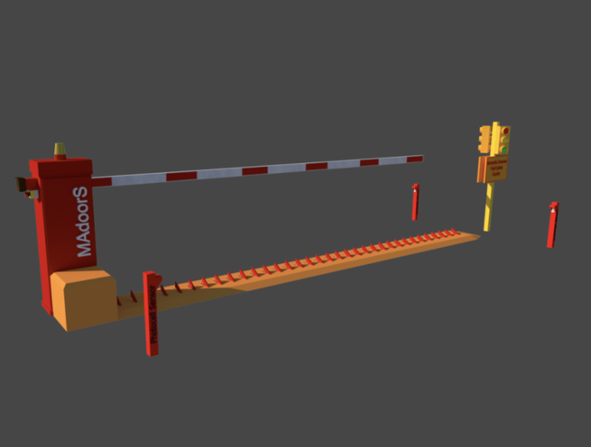
The combination of a tyre killer road spike barrier and a drop arm boom barrier in a single integrated system provides two complementary vehicle access control mechanisms in one installation — the drop arm providing the primary visual and physical access control signal and the tire killer providing the ultimate physical vehicle stopping sanction for unauthorized vehicles that attempt to bypass or drive through the drop arm. This two-level deterrence and stopping capability provides significantly more comprehensive access control than either system alone.
30-Degree Safety Sequence — Spikes Rise After Arm Begins Closing
The 30-degree safety sequence is the defining operational safety feature of the integrated system — the spikes rise only after the barrier arm has passed through 30 degrees of its closing cycle. This sequenced operation ensures that the spike activation always follows the barrier arm warning signal rather than occurring simultaneously — giving vehicle operators the visual warning of the closing arm before the physical tire destruction threat of the rising spikes is presented. The safety sequence prevents spike contact with a vehicle that is still responding to the arm signal.
100% Duty Cycle — High Volume Traffic
The 100% duty cycle specification confirms that the system is engineered for continuous operation without pause or rest periods between cycles — supporting the highest volume traffic access control applications where the combined barrier system cycles hundreds or thousands of times per day without operational degradation or thermal overload. This continuous duty capability makes the integrated system the appropriate specification for the highest-throughput industrial, mining, hospital, airport, and commercial facility access control points.
Two Independent Torque Motors — 1 Second Spike, 2.5-6 Second Arm
The two independent single-phase torque motors provide separate, independently controlled actuation for the spike mechanism and the drop arm — with the 1-second spike speed matched to the rapid deployment requirement of the tyre killer and the 2.5 to 6 second arm speed matched to the smooth, safe movement requirement of the boom barrier. Independent motors allow each component to be optimized for its specific functional requirement without the speed compromise of a shared drive system.
Bidirectional Entry & Exit Protection
The spike barrier provides bidirectional protection — effective against unauthorized vehicles approaching from either direction — covering both unauthorized vehicle entry into the protected facility and unauthorized vehicle exit from a secure zone. Bidirectional protection eliminates the directional limitation of one-way spike systems that protect only against entry or only against exit, providing complete vehicle access control at two-way traffic access points.
Two Power Failure Configurations — Application-Matched Fail-Safe
The selectable power failure configuration allows the fail-safe default state to be matched to the specific operational safety priority of each installation. The boom-down/spikes-up configuration maintains physical vehicle stopping capability during power failure — prioritizing security continuity over free passage. The boom-open/spikes-down configuration provides safe vehicle egress during power failure — prioritizing personnel safety and emergency vehicle access over continued physical blocking. This configuration choice is made at installation based on the specific risk assessment of each facility.
Compact Design — Minimum Excavation
The compact combined system design requires the minimum of excavation work for both the spike mechanism and the drop arm housing — reducing civil works cost, installation time, and site disruption compared to full-scale road blocker and barrier combination systems. Compact installation also minimizes the footprint of the combined system at the access control point, preserving the maximum available clear width and approach visibility.
Surface Mount & Flush Mount Options
Both surface mount — above-ground installation without excavation — and flush mount — below-surface embedded installation — options are available for the spike barrier component, providing installation flexibility for different surface conditions, aesthetic requirements, and operational preferences. Surface mount provides the fastest installation with no excavation. Flush mount provides a lower-profile installation with the spike array below the road surface in the lowered position.
Wide Application Range — Industrial to Military
The 100% duty cycle, bidirectional protection, integrated combined system capability, and configurable power failure modes cover the full range of application requirements from high-volume continuous-duty industrial and commercial facility access control through to the highest-security military installation, embassy, prison, and government facility access control — without requiring application-specific product variants.
OPERATIONAL CYCLE SEQUENCE
Vehicle approach — the vehicle approaches the integrated barrier position. Drop arm barrier signals stop — the barrier arm is in the lowered, blocking position. Access authorization — the vehicle operator presents credentials through the specified access control interface. Access granted — the arm rises and the spikes remain retracted for authorized vehicle passage. Vehicle passes — the authorized vehicle passes through the barrier position over the retracted spike surface. Barrier arm begins closing — the arm motor activates and the arm begins its closing arc. 30-degree trigger — when the arm passes 30 degrees on the closing cycle, the spike motor activates. Spikes rise — the tyre killer spikes rise to the deployed position. Full closure — the arm completes its closing arc and the spikes are fully raised. System ready for next cycle.
Unauthorized vehicle attempt — vehicle approaches and attempts to drive through without authorization. Drop arm is down and spikes are up. Vehicle contact with raised spikes — tires are immediately punctured and deflated. Vehicle immobilized within meters of the barrier position.
ASSEMBLY & INSTALLATION SEQUENCE
Site Assessment & Configuration Selection
Opening width, traffic volume, power failure configuration preference — boom-down/spikes-up or boom-open/spikes-down — installation type — surface or flush mount for spike barrier — access control interface requirements, and motor speed settings are confirmed.
Excavation & Foundation Preparation
Minimum excavation is completed for the drop arm housing foundation and flush-mount spike pit where specified. Surface-mount spike barrier position is prepared without excavation. Electrical conduit routing from power supply to both motor units is installed.
Drop Arm Housing Installation
The drop arm barrier housing is installed and anchored at the specified position. Motor connection and arm pivot mechanism are installed and verified.
Spike Barrier Installation
The spike barrier unit is installed at the specified position — surface-mounted and secured to the road surface, or embedded in the prepared flush-mount pit. Double spike motor connection and spike travel are verified.
Integrated Control System Wiring
The two independent motor control systems are connected to the unified PLC control system. The 30-degree safety sequence trigger is programmed — spike motor activation conditional on arm position sensor confirming 30 degrees of closing travel. Power failure configuration — boom-down/spikes-up or boom-open/spikes-down — is programmed.
Safety Sequence Testing
The 30-degree safety sequence is tested through multiple complete access cycles — confirming that spikes rise only after the arm has passed the 30-degree closing position and not before. Bidirectional spike protection is tested from both approach directions.
Power Failure Configuration Testing
The specified power failure configuration is tested under simulated power loss — confirming correct fail-safe default positions of both the arm and the spikes. Both configuration options are tested to confirm correct programming.
Operational Testing & Handover
Complete operational testing at 100% duty cycle rates, all access control inputs, safety sequences, and power failure modes is conducted. Installation handover documentation is completed.
DEPLOYMENT SCENARIOS & USE CASES
Madoors USA Vehicle Spike Barriers with Drop Arm Barriers are specified for any high-volume, high-security access control point requiring the combined deterrence and physical stopping capability of integrated tyre killer and boom barrier systems.
- Industrial facility and factory high-volume combined barriers
- Mine and quarry vehicle access control integrated systems
- Hospital and healthcare facility vehicle entrance control
- Casino and gaming facility high-security access systems
- Military installation combined spike and arm barriers
- Customs and border control vehicle access systems
- Embassy and diplomatic mission vehicle access control
- Prison and correctional facility vehicle entrance systems
- Government premises and public building access control
- Bank and financial institution vehicle access barriers
- Cash depot and secure currency facility barriers
- Warehouse and distribution center access control
- Airport ground vehicle access control integrated systems
- Gated estate and residential compound access control
- Corporate headquarters and head office vehicle systems