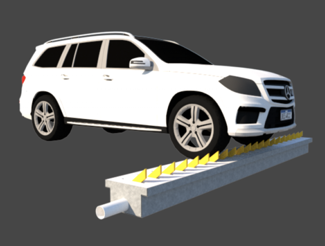
Embedded Type Mechanic Spike Barrier
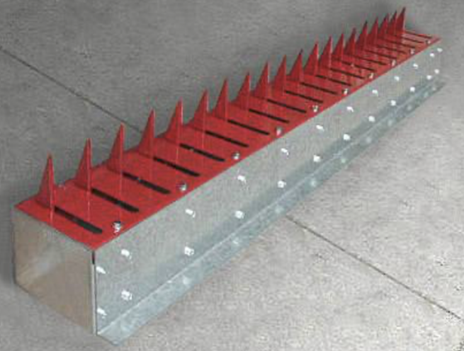
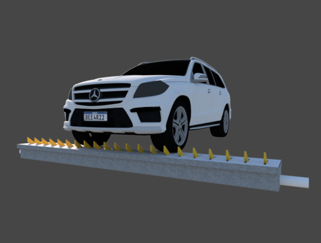
The Madoors USA Embedded Type Mechanical Spike Barrier — Mechanical Tyre Killer — is one of the highest security vehicle access control systems available, providing high-security one-way or directionally controlled vehicle passage at banks, military bases, airports, embassies, and other sensitive facilities against forced and unauthorized motor vehicle entry or exit — without requiring any electrical power supply or electronic control system. Each hardened steel tooth of 32cm full length standing 10cm above ground level operates independently — lowering under the weight of an authorized vehicle passing in the permitted direction and automatically returning to the raised position after the vehicle's tires pass over, while destroying the tires of any vehicle attempting passage from the unauthorized direction immediately and completely.
Available in spring-drive and lever-drive versions with surface-mount and embedded road surface installation options, the Madoors USA mechanical tyre killer provides directional one-way control, bidirectional blocking, or selective partial direction release — entirely through mechanical operation without any electrical infrastructure requirement.
TECHNICAL SPECIFICATIONS
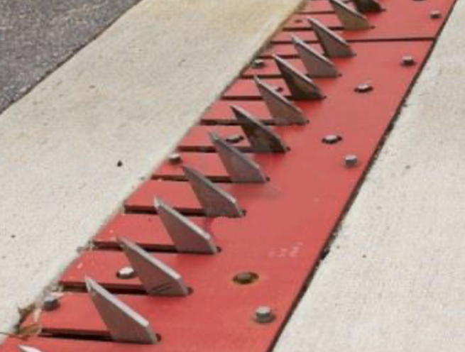
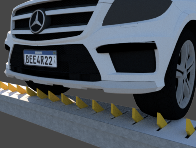
Each tooth of the Madoors USA Mechanical Tyre Killer is manufactured from 10mm steel plate and is attached to a common 16mm diameter hardened steel rod running the full width of the barrier. Each tooth operates individually on the common rod — lowering independently under tire contact and returning to the raised position independently after the tire passes — providing continuous protection coverage across the full barrier width regardless of the specific tire contact position of any individual vehicle.
Tooth dimensions: full length 32cm, standing 10cm above ground level in the normal raised position. The 32cm tooth length and 10cm above-ground height are the operational specifications that ensure complete and reliable tire destruction for all vehicle tire sizes when the tooth engages an unauthorized vehicle attempting reverse passage.
The optional Latch Down Mechanism is installed at one end of the barrier assembly below ground level as a complete integrated assembly with the body — allowing all teeth to be locked simultaneously in the lowered position when authorized two-way passage is required. The below-ground mechanism placement minimizes external environmental effects on the latch mechanism while providing manual drive control for all teeth simultaneously from a single mechanical interface point.
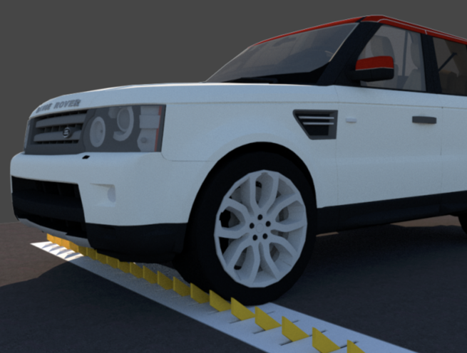
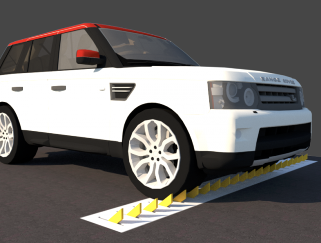
Installation options cover surface mounting over the road surface — where optional rubber humps functioning as speed bumps can be fitted to the surface-mounted model to provide visual warning and traffic calming for approaching vehicles — and embedded mounting at a small depth in the road surface for a lower-profile installation with reduced surface protrusion.
The barrier is available in spring-drive and lever-drive versions. The spring-drive version provides automatic directional operation — teeth lower under vehicle weight in the authorized direction and automatically return to the raised position. The lever-drive version provides three selectable operating modes: spikes raised blocking both directions, spikes lowered and locked for free two-way passage, and spikes raised on one side leaving the other direction free.
KEY FEATURES
No Electrical Power Required — Mechanical Operation
The Madoors USA Mechanical Tyre Killer operates entirely through mechanical spring and lever mechanisms without any electrical power supply, electronic control system, or mains connection. This complete electrical independence makes the barrier immune to power failure, electrical fault, and electronic attack — providing continuous reliable access control in all conditions, including power outages, at remote locations without electrical infrastructure, and in the most demanding outdoor environments.
Individual Tooth Operation — Continuous Coverage
Each 10mm steel plate tooth operates independently on the common 16mm hardened steel rod — allowing individual teeth to lower under tire contact at any position across the barrier width without affecting the raised status of adjacent teeth. This individual tooth operation ensures that partial vehicle overhang positions, narrow vehicle track widths, and irregular tire contact patterns all result in reliable tooth engagement with the tire contact area while the remaining teeth stay raised — providing continuous protection coverage with no gap exploitation possible.
Weight-Activated Automatic Lowering — Authorized Direction
In the spring-drive version, teeth lower automatically under the weight of vehicle tires pressing down in the authorized direction of travel — requiring no operator action for authorized vehicle passage. The vehicle's own weight provides the force to depress the teeth, and the spring mechanism raises the teeth automatically after each tire passes. This fully automatic weight-activated operation eliminates operator management of the barrier for authorized vehicle flow.
Immediate Tire Destruction — Unauthorized Direction
Any vehicle attempting passage from the unauthorized direction encounters the fully raised 32cm hardened steel teeth at 10cm above ground level — which immediately puncture and destroy the vehicle's tires, immobilizing the vehicle within a few meters of the barrier position. The hardened steel tooth construction and 32cm tooth length ensure complete and immediate tire wall penetration for all vehicle tire sizes, with no possibility of a vehicle passing over the raised teeth without immediate tire destruction.
Latch Down Mechanism — All Teeth Locked Simultaneously
The optional Latch Down Mechanism allows all teeth to be locked simultaneously in the lowered position when authorized two-way vehicle passage is required — such as during emergency response, maintenance operations, or controlled access events where two-way passage must be temporarily permitted. The below-ground mechanism placement provides a concealed, environmentally protected latch actuation point that is not accessible to vehicle operators at ground level.
Three Operating Modes — Lever-Drive Version
The lever-drive version provides three selectable operating modes through a single lever mechanism — bidirectional blocking with all spikes raised, full two-way passage with all spikes lowered and locked, and selective one-direction blocking with spikes raised on one side and lowered on the other. These three modes cover the complete range of access control scenarios from maximum security lockdown through to controlled partial access management.
Spring-Drive & Lever-Drive Versions
Two mechanism versions serve different operational requirements. The spring-drive version provides fully automatic directional operation requiring no manual intervention for normal authorized vehicle flow. The lever-drive version provides manually selectable operating mode control for facilities requiring flexible access management across different operational scenarios and time periods.
Surface Mount & Embedded Installation
Two installation depth options accommodate different site conditions and aesthetic requirements. Surface mounting requires no road excavation and allows optional rubber speed bump humps to be fitted for visual warning to approaching vehicles. Embedded installation at a small depth in the road surface provides a lower profile with reduced above-surface protrusion for facilities where minimal surface obstruction between the authorized direction vehicle passes is preferred.
32cm Tooth Length — 10mm Steel Plate Construction
The 32cm full-length hardened steel teeth manufactured from 10mm steel plate provide the combination of height, structural rigidity, and hardness required for immediate and complete tire wall penetration against all vehicle tire types — from passenger car tires through to heavy goods vehicle tires. The 10cm above-ground standing height ensures that the tooth tip penetrates above the tire sidewall contact zone for reliable engagement.
16mm Hardened Steel Common Rod
All individual teeth are attached to the same 16mm diameter hardened steel rod spanning the full barrier width — providing a common structural backbone that maintains tooth alignment and spacing across the full barrier width under the loading conditions of repeated vehicle passes and impact events, while allowing each tooth to pivot independently for individual operation.
INSTALLATION OPTIONS
Surface Mount — With Optional Speed Bump Humps
The barrier is installed over the road surface without excavation, with the base plate secured to the road surface at the specified fixing positions. Optional rubber humps functioning as speed bumps are mounted on the surface-installed model to provide visual and tactile warning to approaching vehicle operators and to reduce approach speed before the barrier position. No road surface preparation is required beyond surface cleaning and fixing hole drilling.
Embedded Mount — Shallow Road Depth
The barrier is installed at a small depth in the road surface — cut into the road at the specified shallow depth and set flush with the surrounding road surface in the lowered position. Embedded installation provides a lower profile with reduced surface protrusion between authorized vehicle passes and a more integrated road surface appearance suitable for facilities where surface-mounted barriers are aesthetically or operationally unsuitable.
ASSEMBLY & INSTALLATION SEQUENCE
Site Assessment & Version Selection
The access control requirement — one-way directional control or multi-mode directional selection — is confirmed. Spring-drive version for automatic directional operation or lever-drive version for selectable mode operation is selected. Surface mount or embedded installation depth is confirmed based on road surface type and available excavation depth. Latch Down Mechanism option is specified where two-way locked passage capability is required.
Road Surface Preparation
For surface mount installation, the road surface is cleaned and fixing hole positions are drilled and prepared. For embedded installation, the road surface is cut to the specified shallow depth and plan dimensions and prepared for barrier body placement.
Barrier Body Installation
The barrier body is installed at the specified road position — surface-mounted and secured with the appropriate fixing hardware, or embedded in the prepared road cut with surrounding infill material compacted to the barrier body profile. Barrier alignment, tooth height verification at 10cm above ground level in the raised position, and flush level in the lowered position are confirmed.
Latch Down Mechanism Installation (Where Specified)
The Latch Down Mechanism is installed at the specified end of the barrier assembly below ground level, integrated with the barrier body. Latch engagement — all teeth locked in lowered position — and release — all teeth free to raise — are tested for correct simultaneous operation across all teeth.
Optional Speed Bump Hump Fitting (Surface Mount)
Rubber speed bump humps are fitted to the surface-mounted barrier body at the specified positions, providing visual and tactile approach warning to vehicle operators.
Direction Verification Testing
The barrier is tested for correct directional operation — authorized direction teeth lowering under simulated tire pressure and automatic return to raised position, unauthorized direction teeth remaining raised under simulated tire contact, and latch mechanism operation where fitted. Lever-drive mode selection is tested through all three operating mode positions.
Operational Handover
Correct directional orientation of the barrier relative to the authorized vehicle travel direction is confirmed and marked. Latch mechanism operating procedure is documented for facility staff. Installation handover is completed.
DEPLOYMENT SCENARIOS & USE CASES
Madoors USA Embedded Type Mechanical Spike Barriers are specified for any vehicle access control point requiring directional tire destruction security without electrical power infrastructure.
- Bank branch and financial institution vehicle exit control
- Military base vehicle perimeter directional access barriers
- Airport vehicle access and service road one-way control
- Embassy and diplomatic compound vehicle access barriers
- Parking facility exit one-way directional spike barriers
- Fuel pump forecourt drive-off prevention barriers
- Government building vehicle access directional control
- Prison and correctional facility vehicle access barriers
- Shopping center parking exit one-way spike barriers
- Hospital and healthcare facility vehicle access control
- Residential estate and gated community vehicle exits
- Corporate campus service road directional barriers
- Port and maritime terminal one-way vehicle access
- Remote location barriers without electrical infrastructure
- Emergency access route directional control barriers