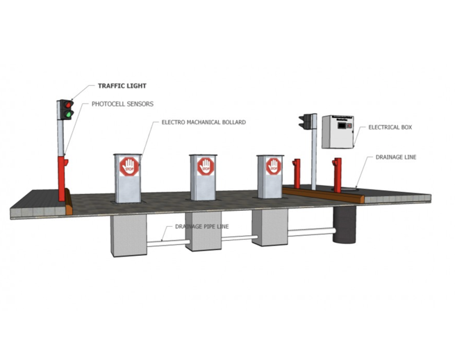
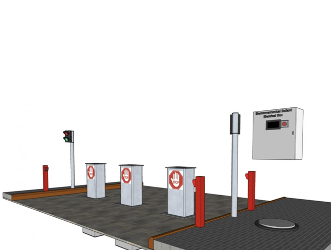
Electro-mechanical Motorized Rising Bollard
The Madoors USA MB-4000 Series Electro-Mechanical Motorized Rising Bollard is an automatic electric anti-ram vehicle barrier engineered to reliably stop and destroy heavily loaded trucks moving at high speeds — operating in all climates with minimal maintenance requirements and a servo electro-mechanical actuator delivering 200 complete up/down cycles per hour at a standard raise time of 3 seconds, reducible to 1.5 seconds with the emergency fast operation circuit. The MB-4000 raises to a 36-inch above-ground vehicle-arresting height with red strobe lights flashing on posts to signal deployed status, and lowers to a completely flush roadway position that will not damage tires, snowplows, or sweeping machines — making it equally suitable for high-security perimeter applications and continuously operated vehicle access control points.
Hot-dip galvanized vault assembly and insert structure, reinforced tubular steel bollard with powder-coated color finish, removable non-skid roadway plates with tamperproof flush bolts, and a fully liftable mechanical insert assembly accessible without heavy equipment make the MB-4000 the most maintenance-friendly high-security rising bollard system available. A 2-year electrical and mechanical warranty from the manufacturing facility departure date is standard, with extended warranty options available.
TECHNICAL SPECIFICATIONS
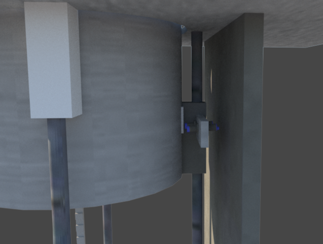
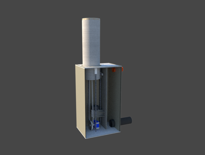
The MB-4000 Series automatic electric rising bollard is constructed from reinforced tubular steel, powder coated in any specified color. The vault assembly is hot-dip galvanized for corrosion protection and requires a 60-inch (approximately 1,524mm) foundation depth. The mechanical structure within the vault is designed as a liftable insert assembly — also hot-dip galvanized — that can be removed from the foundation without heavy equipment for major repairs or maintenance, using only the removable non-skid roadway plates and tamperproof flush bolt access system.
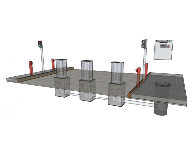
Vehicle-arresting element height in the UP position is 36 inches (approximately 914mm) measured from the roadway surface to the top of the bollard. In the UP position, red strobe lights on the posts flash to provide caution warning to approaching vehicle operators. Impact forces from vehicle collision are transferred through the posts into the foundation structure, providing the structural load path required for anti-ram stopping performance against heavily loaded trucks at high speeds. In the DOWN position, the bollard is completely flush with the roadway surface — presenting no obstruction to tires, snowplows, sweeping machines, or other ground-contact equipment.
The servo electro-mechanical actuator operates the barrier through 200 complete UP/DOWN cycles per hour at normal operating speed — the highest cycle rate available in the Madoors USA bollard range, supporting high-throughput vehicle access control points with continuous round-the-clock operation requirements. Standard raise time is 3 seconds. With the emergency fast operation circuit installed, raise time reduces to 1.5 seconds for immediate threat response.
In the event of power failure, the barrier remains in its last commanded position — a failsafe design that maintains the security state of the bollard at the point of power loss without defaulting to either fully up or fully down. Battery backup operation is available, and manual operation using standard hand tools or a drill fitted with the appropriate drive maintains access management capability without electrical supply.
All major components — actuator, control and logic modules, and cabinet — are built to heavy industrial traffic control requirements and housed in a weather-resistant cabinet engineered for the environmental conditions of the installation site. Control and logic modules are field programmable by a professional installer for the full range of operating requirements including remote control station interface and buried detector integration.
KEY FEATURES
Anti-Ram — Stops & Destroys Heavily Loaded Trucks at High Speed
In the UP position, the MB-4000 presents a certified vehicle-arresting obstacle capable of stopping and destroying heavily loaded trucks moving at high speeds. Impact forces are transferred through the reinforced tubular steel posts into the 60-inch deep foundation — distributing the full vehicle kinetic energy into the structural foundation rather than deflecting or toppling under impact. This structural load path integrity is the engineering basis of the MB-4000's anti-ram stopping performance against the highest vehicle weight and speed attack scenarios.
36-Inch Vehicle-Arresting Height
The 36-inch above-ground height of the raised bollard provides the vehicle-arresting element height required to engage the front bumper, radiator, and engine compartment of any standard commercial vehicle — transferring all stopping force into the vehicle's primary structural mass rather than passing under the vehicle body. This height is the standard specification for anti-ram bollard vehicle-arresting elements in security engineering practice.
200 Cycles Per Hour — High-Throughput Access Control
The 200 complete UP/DOWN cycles per hour capability of the MB-4000 servo actuator supports continuous high-throughput vehicle access control at the most demanding access points — highway toll plazas, busy parking facilities, military base main gates, and commercial facility entrances where vehicles arrive at high frequency throughout all operating hours. This cycle rate far exceeds the capability of hydraulic bollard systems and standard electromechanical alternatives, making the MB-4000 the correct specification for the highest-volume vehicle access control applications.
3-Second Standard Raise — 1.5-Second Emergency Response
The standard 3-second raise time provides fast, responsive bollard deployment for normal high-cycle access control. The 1.5-second emergency fast operation circuit delivers the fastest available bollard deployment for immediate threat response — reducing the time between threat detection and physical vehicle barrier deployment to the minimum achievable with a rising bollard system.
Completely Flush DOWN Position — No Equipment Damage
In the fully lowered position, the MB-4000 is completely flush with the roadway surface — presenting no raised element that would damage vehicle tires, snowplow blades, road sweeping brushes, or any other ground-contact equipment. This flush down position allows full normal traffic flow over the bollard position without speed restriction or equipment protection measures, and eliminates the operational management requirements of partially recessed or exposed bollard systems in the lowered position.
Failsafe Last-Position Design — Power Failure Security
The power failure design retains the bollard in its last commanded position rather than defaulting to either the fully up or fully down position. This failsafe approach preserves the security state of the bollard at the point of power loss — maintaining the raised position if the bollard was up when power failed, and maintaining the lowered position if it was down — without allowing an unauthorized vehicle passage opportunity through unexpected bollard descent or an unintended obstruction through unexpected bollard rise.
Battery Backup & Manual Operation
Battery backup provides continued automatic bollard operation during mains power failure. Manual operation using standard hand tools or a drill with the appropriate drive allows bollard raise and lower without electrical power — maintaining complete access management capability across all power supply failure scenarios.
Hot-Dip Galvanized Vault & Insert Assembly
Both the vault assembly and the liftable mechanical insert assembly are hot-dip galvanized, providing comprehensive corrosion protection throughout the below-grade installation environment. Hot-dip galvanization penetrates all surface areas including cut edges, weld zones, and internal cavities — providing superior corrosion resistance compared to paint or spray-applied coatings at the most corrosion-exposed below-grade components.
Liftable Insert Assembly — No Heavy Equipment Maintenance
The entire mechanical insert assembly is designed as a liftable unit that can be removed from the foundation for major repairs or maintenance without requiring heavy equipment — using only standard tools and the access provided by the removable non-skid roadway plates. This maintenance design approach directly reduces the cost, downtime, and operational disruption of maintenance events throughout the service life of the installation.
Removable Non-Skid Roadway Plates — Tamperproof Access
Non-skid roadway plates secured by tamperproof flush bolts provide safe, anti-slip surface coverage over the bollard vault area and convenient access to maintenance and service points within the vault. Tamperproof flush bolts prevent unauthorized access to the vault interior while maintaining straightforward access for authorized maintenance personnel.
Red Strobe Warning Lights
Red strobe lights on the bollard posts flash when the barrier is deployed in the UP position — providing a clear visual warning to approaching vehicle operators that the barrier is raised and that passage is blocked. The red strobe flash pattern provides maximum visibility under all ambient lighting conditions, including daytime, low-light, and nighttime deployment scenarios.
Field Programmable Control & Logic Modules
The control and logic modules are field programmable by a professional installer — supporting the widest range of operating requirements including single unit, group operation, remote control station interface, buried detector integration, and any combination of the available optional input devices. Field programmability allows the MB-4000 to be configured precisely for the access control protocol of each specific installation without requiring factory reprogramming.
Universal Access Control Interface
Optional input interfaces cover vehicle loop detectors, access control systems, remote hard-wired control stations, radio remote control, card readers, key switches, local guard operator consoles, and any combination thereof — providing complete flexibility for integration with any existing or new access control infrastructure.
Weather-Resistant Cabinet — All Climate Operation
All major components are housed in a weather-resistant cabinet engineered for the anticipated environmental conditions of the installation site. The MB-4000 is specified for reliable operation in all climates — covering temperature extremes, precipitation, humidity, and freeze-thaw cycling encountered across all geographic installation locations.
ASSEMBLY & INSTALLATION SEQUENCE
Site Survey & Foundation Design
Bollard position, foundation depth of 60 inches, soil conditions, and groundwater level are assessed. Multiple bollard group configuration and shared control cabinet position are confirmed. Access control interface requirements and optional input device specifications are confirmed.
Foundation Excavation & Concrete Works
Foundation excavation is completed to 60-inch depth at each bollard position. Reinforced concrete foundation is cast with the vault assembly positioned and anchored during the pour. All electrical conduit and loop detector cable routing is installed within the foundation before concrete completion.
Vault Assembly Installation
The hot-dip galvanized vault assembly is installed in the cast foundation. Vault alignment, level, and flush relationship to the planned roadway surface level are verified.
Mechanical Insert Assembly Installation
The hot-dip galvanized mechanical insert assembly is installed within the vault. Actuator connection, bollard post engagement, and full UP/DOWN travel range are verified. Insert alignment and tamperproof flush bolt positions for roadway plate installation are confirmed.
Non-Skid Roadway Plate Installation
Non-skid roadway plates are installed and secured with tamperproof flush bolts over the vault area. Plate flush alignment with the surrounding roadway surface is verified. Plates are confirmed removable for maintenance access without heavy equipment.
Control Cabinet, Battery Backup & Electrical Connection
The weather-resistant control cabinet is installed at the specified position. Battery backup system is connected and charged. Mains electrical supply is connected to the cabinet. All control and logic module wiring is completed and verified.
Control Module Field Programming
The control and logic modules are field programmed by the professional installer — configuring operating logic, cycle speed, UP/DOWN limits, emergency fast operation circuit parameters, failsafe last-position behavior, and all access control interface inputs for the specific installation requirements.
Optional Input Device Installation & Integration
Vehicle loop detectors, card readers, key switches, remote control receivers, guard operator consoles, and any other specified optional input devices are installed and connected to the control system. All input device responses are tested and verified.
Red Strobe Light Installation & Testing
Red strobe lights are installed on the bollard posts. Strobe activation in the UP position is tested and verified for correct flash pattern and visibility.
Full Operational Testing — 200 Cycle Verification
Complete operational testing across all access control inputs, emergency fast operation, battery backup, manual operation, failsafe power failure position retention, and red strobe warning is conducted. Sustained cycle testing at representative duty cycle rates is completed to verify 200 cycles per hour capability. Two-year warranty documentation is compiled into the project handover package.
DEPLOYMENT SCENARIOS & USE CASES
Madoors USA MB-4000 Electro-Mechanical Rising Bollards are specified for any vehicle access control point requiring high-cycle anti-ram bollard performance with minimal maintenance in all climates.
- Military base and installation main vehicle access control
- Government building and ministry vehicle perimeter bollards
- Embassy and diplomatic compound vehicle access bollards
- Highway toll plaza high-cycle vehicle control bollards
- Airport perimeter and terminal vehicle access bollards
- Critical national infrastructure perimeter bollard systems
- High-volume parking facility entrance and exit bollards
- Petrochemical plant and refinery vehicle perimeter bollards
- Port and maritime terminal vehicle access control bollards
- Shopping center and retail park vehicle access bollards
- Corporate campus and business park high-cycle bollards
- Bank and financial institution headquarters vehicle bollards
- Stadium and arena event vehicle access control bollards
- Prison and correctional facility vehicle entrance bollards
- Border crossing and checkpoint high-cycle vehicle bollards