Please provide your technical specifications and project requirements for the Electro Mechanic Drop Arm Barrier. Our engineers will review your application and provide a detailed manufacturing quote, including exact pricing and lead times.
Electro Mechanic Drop Arm Barrier
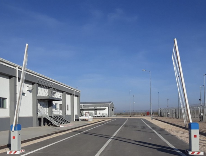
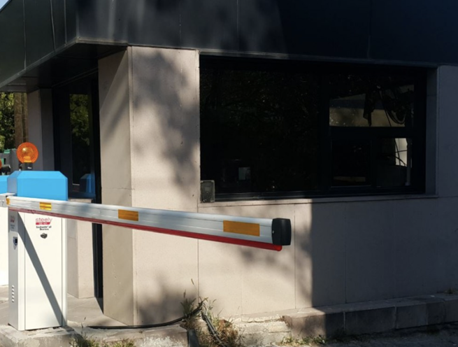
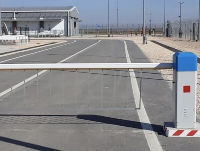
The Madoors USA KBS 30 and KBS 60 Series Electromechanical Drop Arm Barrier is a speed-type rising arm barrier specifically engineered for high-flow traffic environments where intensive continuous usage, harsh environmental conditions, and rapid reliable cycle performance are the primary operational requirements. Designed with a strong electric motor, frequency controller for smooth slow-start and slow-stop operation, and a manual release gear mechanism for power failure operation, the KBS series delivers significantly longer mechanism service life than standard parking barriers through its frequency-controlled smooth operation — eliminating the mechanical shock and wear generated by direct-start motor systems in high-cycle applications.
Compatible with card readers, biometric readers, radio controls, key switches, photocells, inductive loop detectors, and flashing or traffic signal lights, the KBS 30 and KBS 60 integrate with any access control system for complete automated vehicle management at parking facilities, commercial entrances, and high-volume traffic control points.
TECHNICAL SPECIFICATIONS
The Madoors USA KBS 30 and KBS 60 electromechanical drop arm barriers use an electric motor drive with frequency controller — providing variable-speed motor operation that delivers smooth acceleration from rest to operating speed and smooth deceleration from operating speed to the fully open or closed limit position. This frequency-controlled slow-start and slow-stop operation eliminates the mechanical shock loading on the barrier arm, drive mechanism, and housing that occurs with direct motor start-stop systems — significantly extending mechanism service life in high-cycle intensive usage applications.
The drive unit is electromechanical — providing reliable, energy-efficient operation under continuous duty in the hottest environmental conditions. In the event of mains power failure, the barrier arm can be lowered or raised manually using the integrated release gear mechanism, providing safe access management capability without electrical supply and preventing the barrier from remaining locked in the raised or lowered position during a power outage.
The KBS 30 and KBS 60 model designations cover different arm length and barrier opening width ranges — with the specific model selected based on the vehicle lane width, required arm length, and expected daily cycle rate of each installation.
KEY FEATURES
Frequency Controller — Smooth Slow-Start & Slow-Stop
The frequency controller provides variable-speed motor operation — slowly accelerating the barrier arm from the start of each cycle and smoothly decelerating to a complete stop at the end of travel. This slow-start and slow-stop operation eliminates the mechanical shock that conventional direct-start barriers apply to the arm, pivot, and drive mechanism at the beginning and end of every cycle. In high-cycle applications where hundreds of cycles occur daily, the accumulated mechanical shock reduction of frequency-controlled operation directly translates into significantly longer service life for all mechanical components.
Continuous Duty — Harsh Environment Capability
The strong electric motor and frequency-controlled drive system are specified for continuous operation in the hottest environmental conditions without thermal overload or performance degradation. This harsh environment and continuous duty capability makes the KBS series the correct specification for high-flow traffic control points — highway toll booths, high-volume parking facilities, industrial site entrances, and any access point where the barrier operates at very high daily cycle rates in exposed outdoor conditions.
High-Flow Traffic Design
The KBS 30 and KBS 60 are specifically designed for high-flow traffic applications — providing the cycle speed, duty cycle rating, and mechanical durability required for sustained operation at entrances where vehicle throughput is the primary operational requirement. The combination of rapid arm travel speed, frequency-controlled smooth operation, and continuous duty motor specification delivers maximum throughput with minimum mechanical wear at the most demanding traffic control positions.
Manual Release Gear Mechanism — Power Failure Operation
The integrated manual release gear mechanism allows the barrier arm to be lowered or raised by hand during mains power failure — providing complete access management capability without electrical supply. The gear mechanism release is straightforward to operate without specialized tools, and returns to motorized drive engagement when power is restored.
Universal Access Control Compatibility
The KBS barrier control electronics accept inputs from all standard access control devices — card readers, biometric readers (fingerprint and hand shape), radio remote controls, on/off key switches, and any other access control device providing a compatible output signal. This universal input compatibility allows the barrier to be integrated into any existing or new access control system without compatibility constraints.
Safety Accessory Integration
Photocell safety sensors, inductive loop vehicle detectors, flashing warning lights, and red/green traffic signal lights all integrate directly into the barrier control electronics — providing complete vehicle detection, obstruction protection, and traffic management signaling as part of the installed barrier system.
ASSEMBLY & INSTALLATION SEQUENCE
Site Assessment & Model Selection
Vehicle lane width, required arm length, expected daily cycle rate, environmental conditions, and access control interface requirements are assessed. KBS 30 or KBS 60 model is selected based on arm length and duty cycle requirements. Control interface devices are confirmed.
Foundation & Cabinet Installation
The barrier housing foundation pad is prepared and the housing cabinet is positioned and anchored at the specified installation location. Electrical supply conduit and loop detector cable conduit routing are installed during foundation works.
Barrier Arm Installation & Drive Connection
The specified arm type and length are installed on the pivot mechanism. Frequency controller parameters — acceleration ramp, deceleration ramp, and travel limit positions — are programmed for the specific arm length and cycle speed requirement.
Safety System & Access Control Installation
Photocell sensors, inductive loop detectors, flashing lights, and traffic signal lights are installed and connected. Access control interfaces are wired and tested. Manual release gear mechanism operation is tested and verified.
Operational Testing & Handover
Complete operational testing across all cycle modes, access control inputs, safety sensor responses, frequency controller smooth operation, and manual release function is conducted. Installation handover documentation is completed.
DEPLOYMENT SCENARIOS & USE CASES
- Highway and motorway toll booth high-cycle barriers
- High-volume parking facility entrance and exit barriers
- Industrial facility and factory high-flow vehicle access
- Shopping center and retail park high-traffic entrance barriers
- Airport road and cargo facility high-cycle vehicle barriers
- Hospital and healthcare facility parking entrance barriers
- Corporate campus and business park vehicle access control
- Port and maritime terminal high-flow vehicle barriers
- University and educational campus high-cycle entrance barriers
- Residential complex and gated community vehicle access
- Category: Drop Arm Barriers