Name:
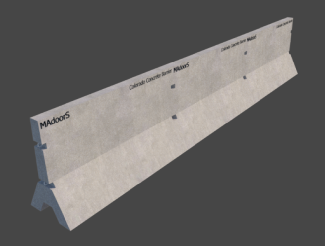
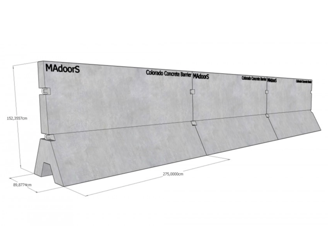
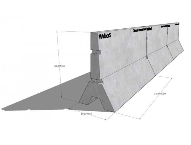
Colorado Concrete Barrier
Part Number:
MDR-8-148
Please provide your technical specifications and project requirements for the Colorado Concrete Barrier. Our engineers will review your application and provide a detailed manufacturing quote, including exact pricing and lead times.
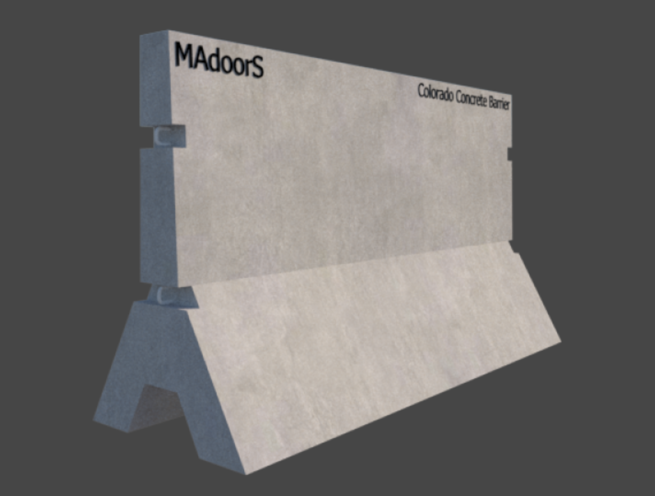
The Madoors USA Colorado Concrete Barrier is manufactured in conformance with the design standards established by the Colorado Department of Transportation (CDOT), providing certified compliance with CDOT requirements for both guardrail Type 7 F-Shape concrete barriers and precast Type 7 concrete barriers across highway, road edge, median, and perimeter safety barrier applications in Colorado and jurisdictions adopting CDOT standards.
TECHNICAL SPECIFICATIONS
The Colorado Concrete Barrier is available in two primary configurations — guardrail Type 7 F-Shape barriers and precast Type 7 barriers — each with different construction methods and pin requirements.
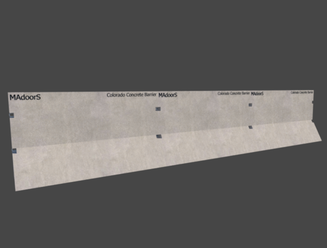
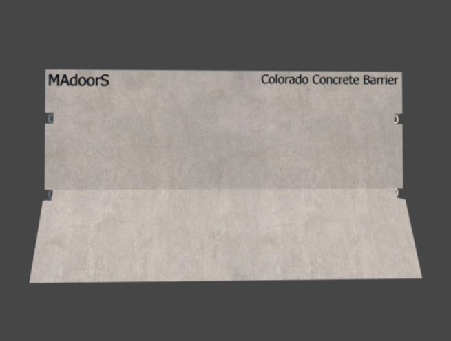
Guardrail Type 7 F-Shape barriers are available as cast-in-place or slip-formed construction. The F-Shape profile is the standard highway median and road edge barrier geometry providing the curved lower face that redirects vehicle tires during impact and prevents vehicle override. Cast-in-place and slip-formed F-Shape barriers are continuous structural elements that do not require connecting pins or stabilization pins between barrier sections.
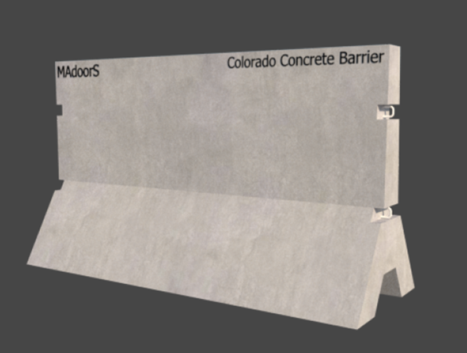
Precast Type 7 barriers are manufactured as individual precast concrete sections that require both barrier connecting pins and stabilization pins to join sections and stabilize the installation.
Connecting pins for precast Type 7 barriers are manufactured from galvanized high-strength ASTM A449 steel and are available in two head configurations. The welded circular washer head version features a round washer that rests on the topmost connecting loop of the barrier section to hold the pin in position. The forged head version provides a one-piece forged head that similarly rests on the connecting loop. Both versions feature a threaded top for removal using a special lifting nut. The forged head version may alternatively incorporate a horizontal hole or a second lip on the head to facilitate removal without the threaded lifting nut method. An optional 1/2-inch bevel may be added to the bottom of either connecting pin style for easier placement into the connecting loop during installation.
Stabilization pins are manufactured from galvanized ASTM A36 steel with a welded washer on one end to provide the bearing surface against the barrier top surface. An optional tapered end is available on the opposite end to assist with driving the pin into asphalt or soil at the barrier installation location. Both connecting pin styles conform to Colorado Standard Plan No. M-606-14, Sheet 2.
KEY FEATURES
CDOT Standards Compliance — Type 7 F-Shape & Precast
The barrier system complies with Colorado Department of Transportation standards for both Type 7 F-Shape and precast Type 7 barrier configurations — providing procurement-compliant barrier systems for CDOT-regulated highway and road projects in Colorado without requiring additional engineering approval for barrier geometry or material specification.
F-Shape Profile — Cast-in-Place & Slip-Formed Options
The Type 7 F-Shape barrier profile provides the standard highway barrier geometry specified by CDOT for median and road edge protection. Cast-in-place construction produces a continuous monolithic barrier section integrated with the road structure. Slip-formed construction uses a continuously moving form to produce a consistent F-Shape profile in a single continuous pass — providing efficient barrier construction for long highway median and road edge installations.
No Pins Required for F-Shape Barriers
Guardrail Type 7 F-Shape barriers — whether cast-in-place or slip-formed — do not require connecting or stabilization pins, simplifying the installation process for continuous barrier runs and reducing hardware procurement requirements for F-Shape barrier projects.
ASTM A449 High-Strength Connecting Pins — Galvanized
Connecting pins for precast Type 7 barrier sections are manufactured from ASTM A449 high-strength steel with full galvanizing for corrosion resistance throughout the service life of the installation. ASTM A449 specification provides the tensile strength required for connecting pins that must maintain barrier section alignment under vehicle impact loading.
Welded Circular Washer & Forged Head Pin Options
Two head style options provide installation and removal flexibility for different site conditions and equipment availability. The welded circular washer head provides a reliable bearing surface on the barrier connecting loop with the threaded removal system. The forged head version provides a one-piece head of superior structural integrity with horizontal hole or second lip removal options as alternatives to the threaded lifting nut method.
Threaded Top — Lifting Nut Removal
The threaded top on both connecting pin styles provides a standardized removal method using a special lifting nut — allowing pins to be withdrawn from the connecting loop without pry tools or impact equipment that could damage the barrier top surface or surrounding pavement. Threaded removal supports clean pin extraction for barrier section repositioning or removal during road maintenance and reconstruction operations.
Optional 1/2-Inch Bevel — Easier Placement
The optional 1/2-inch bevel on the bottom of either connecting pin style guides the pin into the connecting loop during installation, reducing the alignment precision required during pin placement and speeding up the barrier section connecting process — a practical time-saving feature for large-volume precast barrier installation projects.
ASTM A36 Stabilization Pins — Galvanized with Welded Washer
Stabilization pins manufactured from galvanized ASTM A36 steel with a welded washer bearing surface provide barrier stabilization against lateral movement at the installation surface. The welded washer distributes the bearing load across the barrier top surface rather than concentrating it at the pin diameter, preventing local surface damage from pin bearing contact.
Optional Tapered Stabilization Pin End — Asphalt & Soil Driving
The optional tapered end on stabilization pins allows the pin to be driven into asphalt or soil at the barrier installation location without requiring pre-drilled pilot holes — speeding up stabilization pin installation on road surfaces and unpaved ground installations where drilling equipment may not be immediately available.
Colorado Standard Plan M-606-14 Compliance
Both connecting pin styles conform to Colorado Standard Plan No. M-606-14, Sheet 2 — the CDOT standard plan governing connecting pin design and specification for precast Type 7 concrete barrier installations. Conformance to this standard plan ensures that the connecting pins satisfy the CDOT procurement and engineering approval requirements for precast barrier projects without requiring project-specific pin engineering justification.
ASSEMBLY & INSTALLATION SEQUENCE
Barrier Layout Planning
The barrier run geometry, total length, section count, and pin requirements are determined from the project road design drawings. F-Shape cast-in-place or slip-formed sections and precast Type 7 sections are identified for their respective installation zones. Pin quantities — connecting and stabilization — are calculated from the precast section count and spacing.
F-Shape Cast-in-Place Installation (Where Specified)
Formwork is erected along the barrier alignment at the specified F-Shape profile geometry. Reinforcement steel is placed within the form. Concrete is placed and the F-Shape surface profile is formed and finished. The form is removed after concrete achieves sufficient strength for self-support.
F-Shape Slip-Forming (Where Specified)
The slip-form paving machine is set to the CDOT Type 7 F-Shape profile and moves continuously along the barrier alignment, placing, consolidating, and forming the concrete barrier in a single continuous pass without stationary formwork.
Precast Type 7 Section Delivery & Positioning
Precast Type 7 barrier sections are delivered to the installation location and positioned in sequence along the barrier alignment using crane or barrier handling equipment. Sections are set at the specified spacing and alignment, with connecting loop positions aligned between adjacent sections for pin insertion.
Connecting Pin Installation
ASTM A449 connecting pins — welded circular washer or forged head as specified — are inserted through the aligned connecting loops of adjacent precast barrier sections. The optional 1/2-inch bevel at the pin bottom guides the pin into the loops during insertion. Pins are verified as fully seated with the head resting on the topmost connecting loop.
Stabilization Pin Installation
ASTM A36 galvanized stabilization pins are positioned on the barrier top surface at the specified stabilization positions. Pins with optional tapered ends are driven into the asphalt or soil surface at each stabilization position using standard driving equipment. The welded washer bearing surface is verified as flush against the barrier top surface.
Final Alignment & Inspection
The complete barrier run is inspected for section alignment, pin seating, and stabilization pin penetration. Colorado Standard Plan M-606-14 compliance is verified for all connecting pin installations. As-built documentation is completed for the project record.
DEPLOYMENT SCENARIOS & USE CASES
Madoors USA Colorado Concrete Barriers are specified for highway, road, and perimeter safety barrier applications in Colorado and jurisdictions adopting CDOT standards.