

Please provide your technical specifications and project requirements for the Automatic Speed Bump. Our engineers will review your application and provide a detailed manufacturing quote, including exact pricing and lead times.
Automatic Speed Bump
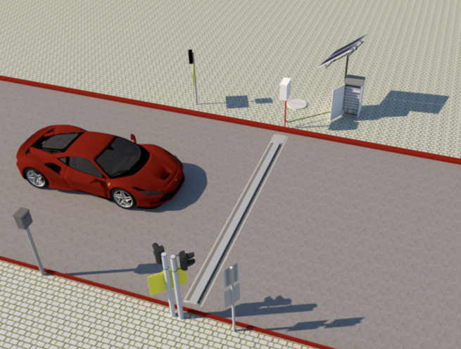
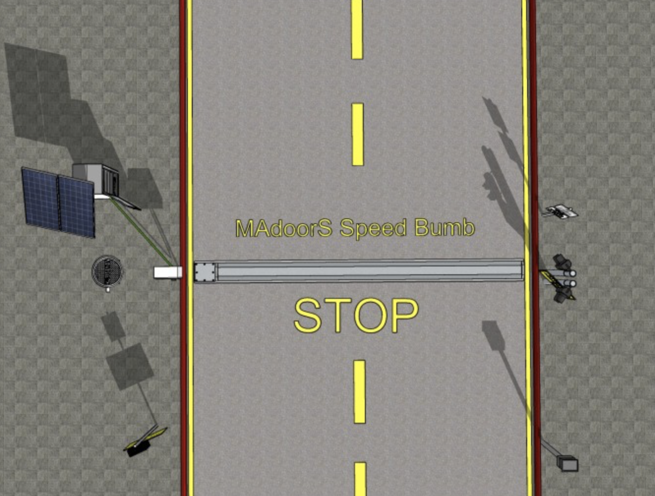
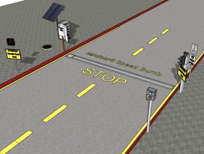
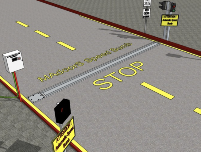
The Madoors USA Automatic Speed Bump is an intelligent, speed-sensitive mechanical traffic calming system installed flush with the road surface, engineered to enforce speed limits automatically without manual intervention — rewarding compliant drivers with smooth, unimpeded passage while delivering a significant jolt to vehicles traveling above the predetermined speed threshold. Unlike conventional fixed speed bumps that slow all vehicles regardless of speed, the Madoors USA automatic smart speed bump responds selectively to vehicle approach speed: vehicles traveling at or below the permitted speed trigger retraction of the bump to a flush road surface position, while vehicles exceeding the speed threshold encounter a raised bump that remains locked in position and delivers the full deterrent impact to the vehicle and its occupants.
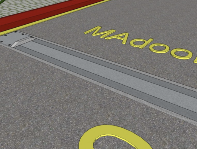
The system is installed set into the road surface with upper edges flush with the surrounding pavement, providing a completely unobtrusive road surface appearance that eliminates the visual disruption, edge marking requirements, and approach signage demands of conventional raised speed bump installations. Shock absorber and spring assemblies are calibrated to the specific installation — accounting for the number of units installed, anticipated traffic speed, and vehicle type profile — providing precise, consistent speed-sensitive response across the full operational service life of the system.
TECHNICAL SPECIFICATIONS
The Madoors USA Automatic Speed Bump is available in three configurations: the motorized automatic speed bump, the automatic smart speed bump, and the automatic speed-sensitive speed bump — each employing the same fundamental speed-detection and selective response principle through different mechanical implementations.
The motorized automatic speed bump incorporates a box-like structure set into the road surface with upper edges flush with the pavement. Two doors are hinged to the box along their opposite edges. Concentric spring and shock absorber assemblies lift the centers of the doors to create the raised speed bump profile. When a vehicle traveling at acceptable speed drives over the unit, the bump folds downward to a position substantially flush with the road surface over a short predetermined time period, allowing the vehicle to pass over the retracted bump with little or no vertical displacement. A vehicle traveling above the permitted speed passes over the unit too rapidly for retraction to occur, resulting in the vehicle encountering the raised bump and experiencing a significant jolt.
The automatic speed-sensitive speed bump incorporates a base plate with a front plate hingedly connected to it and a spring that biases the front plate toward the raised position as default. A speed-sensitive lock mechanism locks the front plate in the raised position when impacted by a vehicle tire traveling at or above the predetermined speed threshold. When vehicle speed is below the threshold, the front plate is not locked — it collapses to a horizontal position under the vehicle's weight and the vehicle passes without experiencing a bump. When speed is at or above the threshold, the lock engages and the front plate remains raised, delivering the deterrent impact.
Shock absorber and spring assembly strength is determined by the number of units installed, the anticipated traffic speed range, and other site-specific factors, with the system calibrated for each installation to ensure consistent speed-sensitive response at the specified speed threshold.
KEY FEATURES
Speed-Selective Response — Compliant Vehicles Pass Smoothly
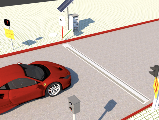
The defining operational characteristic of the Madoors USA Automatic Speed Bump is its selective response to vehicle speed. Vehicles traveling at or below the predetermined speed threshold trigger retraction or collapse of the bump to the flush road surface position — passing over the unit with little or no vertical displacement and no discomfort to occupants. This selective response eliminates the universal speed penalty of conventional fixed bumps that slow emergency vehicles, delivery trucks, and compliant drivers to the same degree as speeders — making the automatic speed bump the preferred specification for roads where emergency vehicle access, delivery operations, and public transport routes require unrestricted passage for compliant speed traffic.
Speed-Sensitive Lock Mechanism — Speeding Vehicles Encounter Full Bump
When a vehicle tire impacts the front plate at or above the predetermined speed threshold, the speed-sensitive lock mechanism engages immediately and locks the front plate in the raised position — ensuring that the speeding vehicle cannot deflect the bump downward and encounters the full raised profile, delivering a significant jolt to the vehicle and its occupants. This automatic locking response requires no electronic detection, no external power trigger, and no operator intervention — the mechanical speed-sensitive lock responds directly and instantaneously to tire impact velocity.
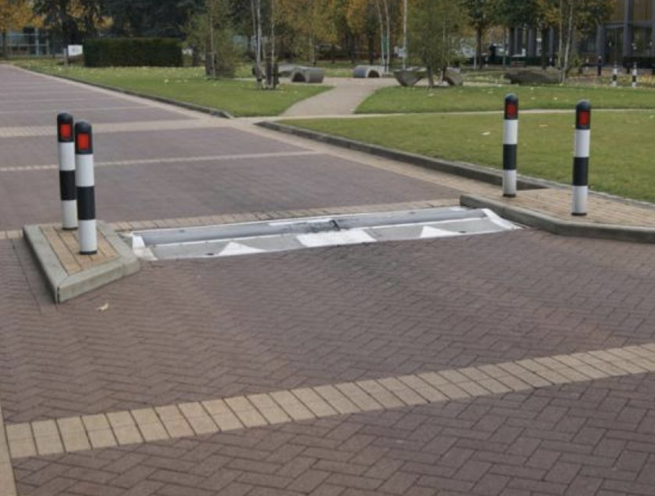
Flush Road Surface Installation — No Visual Obstruction
The speed bump is installed set into the road surface with upper edges flush with the surrounding pavement, providing a completely level road surface appearance when the bump is in the retracted or collapsed position. The flush installation eliminates the visual disruption of raised speed humps, reduces approach signage requirements, and provides a professional, unobtrusive road surface integration that is particularly appropriate for private roads, car parks, facility entrances, and security checkpoint approaches where the aesthetic character of the road environment is a design consideration.
Concentric Spring & Shock Absorber Assemblies
The spring and shock absorber assemblies provide controlled, calibrated mechanical response across the full bump raise, hold, and retract cycle — absorbing the impact energy of vehicle tire contact, maintaining the raised bump position against vehicle deflection attempts at above-threshold speeds, and controlling the retraction rate to the predetermined fold-down period for below-threshold vehicle passes. Assembly strength and calibration are determined for each installation based on the number of units, anticipated traffic speed, and vehicle weight profile.
Calibrated to Installation-Specific Parameters
The shock absorber and spring assembly strength is calibrated specifically for each installation — accounting for the number of units installed in the road, the anticipated range of vehicle speeds at the location, expected traffic volume, and the types of vehicles using the road. This installation-specific calibration ensures consistent, reliable speed-sensitive response at the precise predetermined speed threshold for the specific traffic conditions of each deployment location.
Predetermined Speed Threshold — Customizable
The speed threshold at which the bump engages or retracts is predetermined and customizable for each installation, allowing the system to be calibrated to any specific speed limit relevant to the installation location — from low-speed private road and car park applications through to higher-speed road environments where the threshold must match the posted speed limit. Customizable threshold calibration allows a single product family to serve the full range of speed limit enforcement applications.
Hinged Door System — Balanced Controlled Movement
The hinged door configuration of the automatic smart speed bump variant uses two doors hinged along opposite edges of the box structure, with spring assemblies lifting the door centers symmetrically to create a balanced, consistent bump profile. The symmetrical hinged door movement provides even load distribution across the bump structure during vehicle contact, extending mechanical service life under the repeated loading cycles of continuous traffic operation.
No Manual Intervention — 24/7 Automatic Operation
The automatic speed bump operates entirely mechanically without requiring electrical power, manual reset, or operator intervention for normal speed-sensing and response operation. This self-contained, continuous automatic operation provides 24/7 speed enforcement at the installation location regardless of staffing levels, power supply availability, or operational hours — delivering consistent speed limit enforcement across all traffic conditions throughout the day and night.
Multiple Unit Configurations
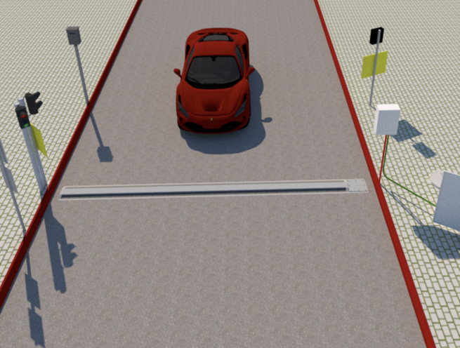
Multiple automatic speed bump units can be installed across the road width in coordinated configurations, with the number of units and their positioning calibrated to cover the full vehicle track width and provide consistent bump response across all vehicle widths — from motorcycles to wide commercial vehicles — without gaps in coverage that could allow vehicles to avoid the bump by track positioning.
ASSEMBLY & INSTALLATION SEQUENCE
Site Assessment & Speed Threshold Calibration
Road surface type, installation location geometry, anticipated traffic speed range, vehicle type profile, and number of units required for full lane width coverage are assessed. Speed threshold for the installation is confirmed. Shock absorber and spring assembly strength calibration is specified based on the installation-specific parameters.
Road Surface Excavation & Box Installation
Road surface is cut and excavated to the specified depth and plan dimensions for the bump box structure at each unit position. The box-like housing structure is set into the excavation with upper edges positioned flush with the surrounding road surface. Foundation and drainage provisions are completed within the installation recess.
Spring & Shock Absorber Assembly Installation
Concentric spring and shock absorber assemblies are installed within the box housing at the specified positions for the chosen bump variant. Assembly pre-load and calibration settings are set to the installation-specific parameters confirmed in the site assessment.
Door or Front Plate Installation & Hinge Setting
Hinged doors or front plate are installed onto the box housing at the specified hinge positions. Door or plate balance, hinge torque, and flush surface alignment in the retracted position are verified. Spring bias toward the raised position is confirmed.
Speed-Sensitive Lock Mechanism Installation & Calibration (Speed-Sensitive Variant)
The speed-sensitive lock mechanism is installed and calibrated to engage at the predetermined speed threshold. Lock engagement at threshold speed and release below threshold speed are tested and verified through controlled tire impact testing at calibrated approach speeds.
Surface Reinstatement & Flush Verification
Road surface is reinstated around the installed bump units, with joint lines sealed and surface level verified flush with the surrounding pavement at all bump perimeter edges. Surface finish and edge transitions are inspected for smoothness and level alignment.
Operational Testing & Speed Response Verification
Full operational testing is conducted across multiple vehicle passes at speeds below, at, and above the calibrated threshold. Retraction response for below-threshold vehicles and lock engagement for above-threshold vehicles are verified. Bump profile height, retraction time, and jolt intensity are assessed against the installation specification.
DEPLOYMENT SCENARIOS & USE CASES
Madoors USA Automatic Speed Bumps are specified for any road or access route environment where selective speed enforcement — smooth passage for compliant vehicles, deterrent response for speeding vehicles — is required.
- Private road and estate internal road speed enforcement
- Car park and parking facility speed control
- Security checkpoint and facility entrance approach speed management
- Hospital and healthcare campus internal road speed control
- School and educational campus access road speed enforcement
- Industrial facility and logistics park internal road speed control
- Residential estate and gated community road speed management
- Airport landside road and car park speed enforcement
- Hotel and resort driveway and access road speed control
- Shopping center and retail park access road speed management
- Military base and facility internal road speed enforcement
- Emergency vehicle access route — compliant speed pass-through
- Construction site access road vehicle speed management
- Stadium and arena event access road speed control
- Category: Road Blocker